- Subject Code : 300736
- University : Western Sydney University My Assignment Services is not sponsored or endorsed by this college or university.
- Subject Name : Design
MAJOR DESIGN ASSIGNMENT
Part: 2 Analysis and design
Design Information and Requirements:
-
Concrete compressive strength, f’c = 32 MPa
-
Modulus of Elasticity of concrete, Ec = 30,000 MPa
-
Yield strength of longitudinal reinforcing steel, fsy = 500 MPa (Use N class bar)
-
Yield strength of transverse reinforcing steel, fsy.f = 400 MPa
-
Modulus of Elasticity of steel, Es = 200,000 MPa
-
Concrete density = 25 kN/m3
-
εcs = 600 με; ψs = 0.7 and ψl = 0.4
-
Superimposed dead load = 3.0 kPa
-
Consider self-weight
-
Slab live load = 3.0 kPa across the floor
-
Columns are 400 mm x 400 mm
-
Beam widths are fixed at 400 mm
-
Slab depth is 200 mm
-
Concrete slabs are supposed to be built monolithically with the supporting beams; therefore, the beams must be designed as L or T-beams.
Calculation and data collection:
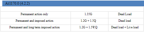
Standard load combinations – AS1170.0 (section 4.2.2) by considering strength criteria
The combinations below are used to design office building structure and achieve M*, V* and N*.
There are other loads as well such as wind load, earthquake imposed load etc. but it neglected as it was not used in the design specification
Serviceability limit state
According to AS/NZS1170.0:2002, Section 4: Combinations of actions, table 4.1, page 17, shown in figure 3 below:

Figure 3: Short-Term, Long-Term and Combination factors, as shown in Table 4.1 in AS/NZS1170.0:2002
Short-Term effect also referred to as “immediate deflection” will be:
G+ sQ
Long-Term effect, which is the part of deflection that occurs due to shrinkage of concrete and due to creep:
G+ lQ
Both load combinations are used to find M*, V* and N* for deflection.
Load calculation
Structural Analysis:
Dead loads:
The following diagram consider for calculating beams self-weight and square area 400 x 400 mm

Assuming, bef=1200
Depth of section = 1000 mm
Density x Cross sectional area of the beam = force per m of the beam.
P x A = F/m
24 kN/m3 x (0.4m x 0.8m) = 7.68 kN/m
Slab self-weight:
By considering internal beams, the uniform distributed load has doubled the external beam uniformly distributed load which demonstrates as following by considering internal beam should doubled.

Density x width x thickness = force per m of the beam.
p x b x t = F/m
Critical slab load section for external beams:
24 kNm3 x 3.5m x 0.2m = 16.8 kN/m
Superimposed Dead load:
The super imposed load will be = 1 kPa x 3.5 = 3.5 kNm
Imposed load considered total dead load = dead load + self-weight
Live Loads
Floor Slab Live Load
Using the AS1170.1 T3.1 B and given that the criteria mentioned was for building construction for a general load value of 3kPa to obtain the live load. 3kPa was applied to each floor of the structure.
The live load on each floor, transferred to each internal beam to give:
3kPa x 3.5m = 10.5 kN/m.
The live load on the floor slabs transferred to the External Beams will be:
3kPa x 3.5m2 = 5.25 kN/m
Roof Slab Live Load
Table 3.1 of AS1170.1 was used to obtain the live load of the roof slab, using this table, the live load was determined using the equation below.
Q (kPa) = greater of (1.8A + 0.12) or 0.25
Plan A projects the supported surface area of the roof of each member in square meters.
A (the area supported by the beam)
A = 3.5m x 15m (quarter of slab) = 52.5m2
1.852.5+0.12 = 0.154
Q = greater of: 0.168 or 0.25, Therefore Q = 0.25 kPa
Peak live load on the roof slab will be:
0.25 kPa x 3.5m = 0.875 kN/m
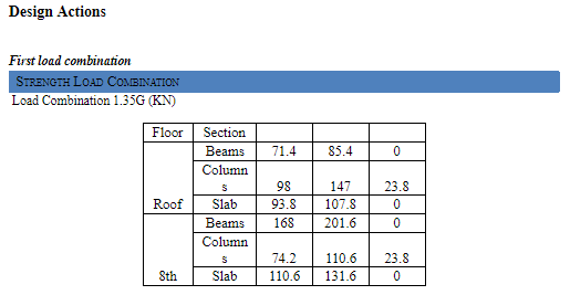
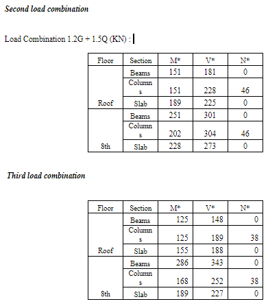
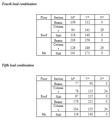
Bending moment and shear force diagrams:
The following is provided maximum bending moment and shear force daigram for the building members. The daigram obtained by the different strength and serviceabilty loads respectively. These are located on the 3rd floor.
Beams
Maximum Load
BMD

SFD
Strength Load 1.35G
BMD & SFD

Strength Load 1.2G+1.05Q
BMD & SFD

Serviceability load: -1.2 + 0.7 Q
BMD & SFD

Serviceability load: -1.2 + 0.4 Q
BMD & SFD

SLAB
Maximum load: 1.2G + 1.5 Q
BMD & SFD

Strength load: 1.35 Q
BMD & SFD

Strength load 1.2G + 1.05 Q
BMD & SFD

Serviceability load: -1.2 + 0.7 Q
BMD & SFD

Serviceability load: 1.2G + 0.4 Q
BMD & SFD

Column:
Maximum Load
AFD

Strength load 1.35G
AFD

Strength load 1.25G + 1.06Q
AFD

Strength load: -1.25 + 0.7Q

Strength Load :

Outcome
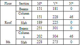
From the obtained value at different condition, the design assessment can completed by ensuring the beam, columns and slab suitability by considering force magnitude . The effective load combination is as 1.2G + 1.5Q and obtained parameter as following i.e. M*,V*,N*
Get It Done! Today
1,212,718Orders
4.9/5Rating
5,063Experts

Highlights
- 21 Step Quality Check
- 2000+ Ph.D Experts
- Live Expert Sessions
- Dedicated App
- Earn while you Learn with us
- Confidentiality Agreement
- Money Back Guarantee
- Customer Feedback
Just Pay for your Assignment
Turnitin Report
$10.00Proofreading and Editing
$9.00Per PageConsultation with Expert
$35.00Per HourLive Session 1-on-1
$40.00Per 30 min.Quality Check
$25.00Total
Free- Let's Start


