- Subject Code : ICT-101
- University : Australian Institude of Business My Assignment Services is not sponsored or endorsed by this college or university.
- Subject Name : Engineering Mathematics
Application of Algorithm and Flow Chart in Binary Arithmetic System
Table of Contents
Introduction.
Rationale.
Flow Chart of the Application.
Algorithm.
Trace Table.
Conclusion.
References.
Introduction
Gottfried Leibniz discovered a special number system that consists of two digits only 1 and 0. This new number system is known as Binary. Like the known number system, Decimal, Binary system also permits arithmetic operations. For its unique Boolean property, the system is used in digital circuits (Gole, Chatburn & Jurecki, 2019). The computer is a digital device. Hence, the operations in a computer are performed by binary arithmetic. Here, a program will be designed to perform a binary operation.
Rationale
The chose topic is an arithmetic operation in the binary number system. Computer programming requires operation during a program. The program, however, is dependent on basic hardware systems. Registers store the actual value in terms of 1 and 0. Therefore, the computer performs the ultimate program in binary methods. The topic related to the fundamental system of computation and it challenges the knowledge of a developer at a fundamental level. Therefore, I have chosen this topic. The BCD, however, is a fundamental operation. But the use of BCD is limited for some programming (Qu, et al., 2017). Whereas, the use of binary arithmetic is universal. There is plenty of binary arithmetic available in the textbook. However, we shall discuss the adder/subtractor in this module as it has been globally used in modern architecture.
Flow Chart of the Application
The fundamental sense of the application is very easy. It has a switch that is enabled by 1 or disabled by 0. If 1 is applied to it the application performs subtraction. The subtraction, although, is performed when 0 is applied to the switch.
To understand the flow chart, we need to understand one basic theory of 2’s complement
If A is Boolean variable and B is another Boolean variable then we can implement A – B by using the formula A + (2’s complement of B) = A + Bc+1. Apart from this, if B is exclusively or with 1 then it provides Bc(Donzellini et al. 2019).
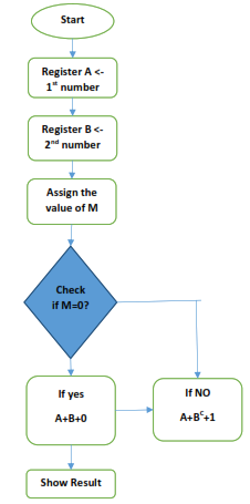
Figure 1: Flowchart of the program
Algorithm
Let us consider it is a 4-bit operation where each bit is assigned in a register as A0, A1, A2, and A3 respectively. Similarly, the bits in B are assigned in the same way. Each of the addition will be performed on similar bits (Marpe, et al., 2016). For example, A0 will operate with B0 if any carry is generated then it will be passed to the next block.
The steps are mentioned below:
Step 1: Assign four different bits to consider it as a complete register A
Step 2: Assign another four bits to consider as register B
Step 3: Assign a third variable as a switch and the fourth variable as carrying
Step 4: Initialize the values in A and B
Step 5: Initialized the value in carrying as zero as default
Step 6: initialize a counter as 3
Step 7: Ask for a request to select the operation.
0 - for addition
1 - for subtraction
Step 8: Enter the choice as value of the switch
Step 9: Perform the given operation in the present block
Value of B is EXOR with switch and then added with A and carry
Step 10: Generate a result and carry
Step 11: reduce the value of the counter by 1 and check if the value of the counter is zero
If yes, then move to step 12
If no, then move to the next block and go to step 9
Step 12: Operation is done successfully. So, collect the result
Step 13: Stop
If the above algorithm is followed, the user will get five bits at the output. Bits are derived from the result of each operation and the ultimate carry of the operation. For example, if S be the be sum then S0, S1, S2, S3, and S4 will be considered as thee complete sum along with a single bit carry (Kuruvila et al. 2017).
Trace Table
In the first case, we have considered the values in A and B as given below
Consider A has 1001 as A3 A2 A1 A0
And b has 1000 as B3 B2 B1 and B0
|
Count |
A |
B |
M = B EXOR Switch |
Switch |
Previous carry |
S = A +M + Switch + carry |
Generated Carry |
|
3 |
A0 = 1 |
B0 = 0 |
0 |
0 |
0 |
1 |
0 |
|
2 |
A1 = 0 |
B1 = 0 |
0 |
0 |
0 |
0 |
0 |
|
1 |
A2 = 0 |
B2 = 0 |
0 |
0 |
0 |
0 |
0 |
|
0 |
A1 = 1 |
B1 = 1 |
0 |
0 |
0 |
0 |
1 |
Table 1: First Trace table
Hence, the result will be 1 0 0 0 1. The result is correct so far
In the second case:
Considering the value of A as 1101 as A3 A2 A1 and A0 respectively and 1001 in Register B.
|
Count |
A |
B |
M = B EXOR Switch |
Switch |
Previous carry |
S = A +M + Switch + carry |
Generated Carry |
|
3 |
A0 = 1 |
B0 = 1 |
0 |
1 |
0 |
0 |
1 |
|
2 |
A1 = 1 |
B1 = 0 |
1 |
1 |
1 |
0 |
1 |
|
1 |
A2 = 0 |
B2 = 0 |
1 |
1 |
1 |
1 |
1 |
|
0 |
A1 = 1 |
B1 = 1 |
0 |
1 |
1 |
0 |
1 |
Table 2: Second Trace table
Thus, the result is 0100 with carrying value 1. They carry 1 determines the positive result after the subtraction. If the value of carrying would have been 0 then this program would fail to provide the proper result.
Conclusion
As mentioned in the assignment a program has been designed that can perform binary arithmetic operations. The complete digital sense has been applied here to measure addition and subtraction in a bitwise level. The task, however, has limitations to solve negative values in the subtraction process. The solution will be the addition of a complementary program at the end. Therefore, it opens the possibility of future work.
References
Donzellini, G., Oneto, L., Ponta, D., &Anguita, D. (2019). Numeral systems and binary arithmetic. In Introduction to Digital Systems Design (pp. 79-113). Springer, Cham.
Gole, S. E., Chatburn, R. L., & Jurecki, M. (2019). Dissemination of Information for a New Protocol: Flow Chart vs Text Based Algorithm.
Kuruvila, J. S., VL, M. L., Roy, R., Baby, T., Jamal, S., & Sherly, K. K. (2017). Flowchart Plagiarism Detection System: An Image Processing Approach. Procedia Computer Science, 115, 533-540.
Marpe, D., Kirchhoffer, H., Siekmann, M., & Bartnik, C. (2016). U.S. Patent No. 9,312,881. Washington, DC: U.S. Patent and Trademark Office.
Qu, M., Cui, N., Wu, X., & Tao, Y. (2017). A Novel Algorithm of Error Check and Code Generation for Structured Flowchart. Journal of Harbin Institute of Technology (New Series), 24(4).
Sze, V., & Budagavi, M. (2017). U.S. Patent No. 9,584,802. Washington, DC: U.S. Patent and Trademark Office.
Remember, at the center of any academic work, lies clarity and evidence. Should you need further assistance, do look up to our Engineering Mathematics Assignment Help
Get It Done! Today
1,212,718Orders
4.9/5Rating
5,063Experts

Highlights
- 21 Step Quality Check
- 2000+ Ph.D Experts
- Live Expert Sessions
- Dedicated App
- Earn while you Learn with us
- Confidentiality Agreement
- Money Back Guarantee
- Customer Feedback
Just Pay for your Assignment
Turnitin Report
$10.00Proofreading and Editing
$9.00Per PageConsultation with Expert
$35.00Per HourLive Session 1-on-1
$40.00Per 30 min.Quality Check
$25.00Total
Free- Let's Start


